Time to read: 7 min
Fillets are one of those mysterious design features for which there seem to be no clearly defined rules. Either a part is entirely devoid of fillets, and most or all edges are well-defined, or the part’s designer decided to take the opposite route, and every single edge and corner is rounded with some size of fillet radius. Fillets are added to increase the strength (by reducing the stress concentration) of the edge of a part or improve the part’s look.
There are two components of fillet engineering: designing fillet geometry and designing fillet machining. A fillet is created between the adjacent lines and faces in 2D and 3D CAD models, curving the surfaces between two lines or planes. In machining, a fillet occurs along the part’s edge and is most likely made with a CNC fillet tool such as a corner rounding end mill tool. This end mill cutter fillet machine tool is programmed to follow the edge of the part and it creates a high-quality fillet. Fillets are still useful and even increasingly relevant in 2023, especially when parts are designed for CNC machining. This article will discuss the cases in which fillets are not beneficial, optimal, or necessary (hint: corner fillets), so you can start making your designs more cost-effective and manufacturable.
Fillets vs Other Design Features
Fillets can be easily confused with other design features such as corner radiuses, chamfers, and bevels. All these features create a similar design whereby a sharp edge is broken. A fillet is a rounded corner or transition between two surfaces in engineering and design. They are typically used to smooth out sharp edges and corners, improve the appearance of a part, and reduce stress concentrations in areas where two surfaces meet.
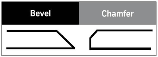
Fillets differ from chamfers and bevels because those features don’t have a radius, whereas fillets do. A chamfer is typically a 45-degree angle added to the edge of a feature design. While a bevel is a slope from a horizontal or vertical edge. A fillet radius rounds inside corners and a corner radius rounds an external corner of the manufactured part.
When To Avoid Using Fillets
Before discussing the optimal utilization of fillets, it’s important to explore where the usage of fillets is not beneficial to your overall part design. Unnecessarily adding fillets could result in higher costs without any added benefit.
Don’t Design Fillets for 3D Printed Parts
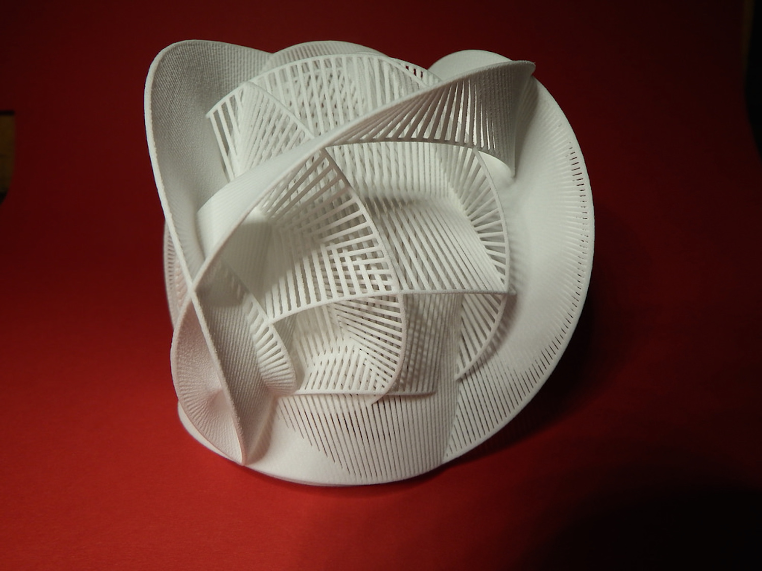
Because 3D printing is an additive process, there’s no need to design a part assuming a tool will need to move around it and remove material, so designers have more freedom to utilize intricate and unusual geometries. Fillets are sometimes added for stress relief in areas of sharp geometry changes, but beyond that, there’s little need for them. Pockets and internal features on printed parts can be angular or sharp-cornered, and you can even have cavities that are completely enclosed by surrounding material!
Also, keep in mind that if you’re using 3D printing for prototyping and plan to move away from 3D printing towards another process, such as CNC machining, you must start planning for the limitations of that second process early on, to save time and money down the road.
Don’t Design Fillets for Bottom Edges
Filleting the bottom edges of pockets, walls, blind holes, or boss features can be used to improve the aesthetics of a part or add strength to features (by reducing stress concentrations). However, fillets in these locations require the use of a ball endmill and will always make your part more expensive than square-bottomed features. This is because programming such a geometry usually requires 3D machining operations (which take longer to dial in). Also, ball endmills are more fragile than their square counterparts and remove material at a much slower rate.
And, it turns out that modification of other geometric features, such as hole depth or proximity of the hole to other volume-removing features, impacts the stress at the bottom of the hole or cavity more than a fillet at the bottom. Also, a design change to modify these features is significantly more cost-effective than adding a complex fillet at the bottom of the cavity. For more information on how the stress concentration within a hole’s geometry is calculated, check out the equations here.
A Note About CNC Machining Fillets
While the possibilities are endless for CNC machining various geometric features, remember that CNC fillets on a CNC machined part add programming and machine time — and therefore cost. The advantages of fillet engineering are specific for each part of your CAD design. However, fillet edges are typically used to remove stress concentration at corners or edges.
To reduce the cost of fillet manufacturing, you can create them without the use of CNC machining. Parts can be fillet welded to create lap, corner, and T joints. Weld metal is placed in these corners to secure these joints, and a fillet weld is created at the corners.
Optional Uses for Fillets
The following sections discuss examples where fillets optimize mechanical designs.
Cosmetic Face Edges
When designing a part with cosmetic faces, CNC filleting the edges of these areas give your part the appearance that its faces blend seamlessly together, rather than transitioning harshly. Since cosmetic fillets don’t improve mechanical or strength properties, you should add cosmetic fillets after the rest of the geometry is determined. These features should be used carefully because they increase the cost of the machined assembly.
When Fillets Improve Handling and Safety
Adding fillets can prevent injuries from sharp edges if your parts will be handled frequently, especially if they made of metal. It’s standard practice for machinists to break all sharp edges anyway, so unless you desire perfectly radiused edges, or your parts have ergonomic features with radiused areas, you can refrain from specifying a filleted radius to reduce costs. Radiuses are designed to eliminate sharp edges in CNC machined parts, and parts may be geometrically designed to eliminate these sharp edges and protect those who will handle the parts in the future.

Pin/Fastener Insertion
Getting a dowel pin to engage with a kit press-fit hole or a fastener to align with its female threaded mate can be tricky for tight fits. Usually, a small chamfer (aka: a bevel) is added around the edge of the hole to aid in insertion, although a fillet can also help if desired.
A filleted hole circumference can prevent the movement of a screw and bolt and it is also the best design for pin insertion. When a pin, screw, or bolt is needed, a chamfer is the better option. A chamfered corner, the preferred CAD design for screws, bolts, and pins, provides easier insertion and is hidden from the stress that an external fillet endures as the chamfer corners are hidden within the part. Chamfered corners endure natural wear due to their sharper corners, but are better suited to fitting mated parts together with screws, bolts, or pins. Pro-Tip: Check out our Press Fit Calculator if you’re struggling with a press-fit application.

Where Fillets are Necessary
This final section explores three cases in which fillets are required for a part to be optimally machined.
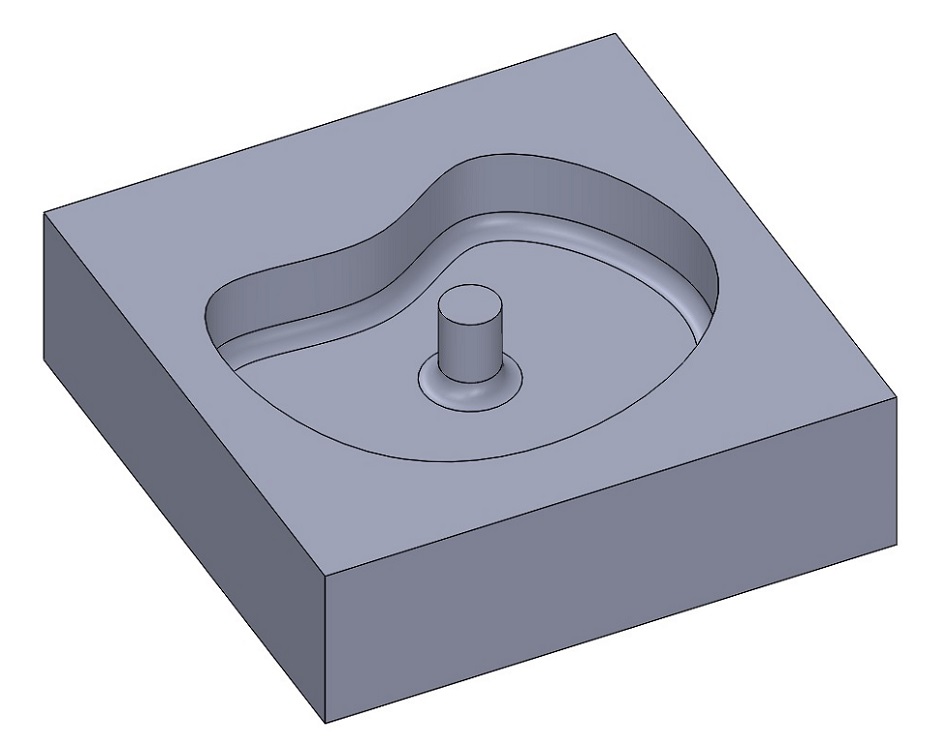
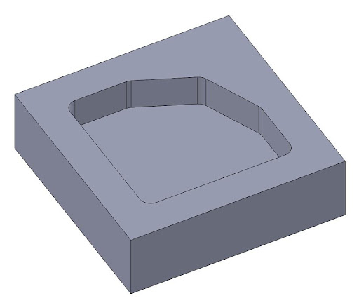
Internal Edges Between Planar Faces
To cut via high-speed rotation, all CNC tooling is round and axially symmetric, so cutting a square corner between two vertical walls is impossible. Any edge where two vertical walls meet at an angle less than 180° requires a fillet, and adding such fillets is the most common piece of DFM feedback we provide for CNC parts. Note: not all CNC mill tooling is axisymmetric (think fly cutters), and most CNC lathe tooling isn’t either.
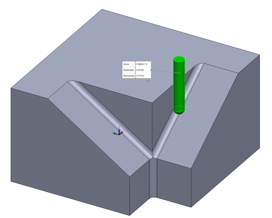
Internal Edges Between Angled/Organic Surfaces
Edges between angled or organic surfaces with less than 180° between them also need fillets. If these edges aren’t perfectly vertical, they’ll be cut with a ball endmill, and the radius of that tool is the smallest fillet size that can be left between the surfaces.
Vertical Wall + Angled/Curved/Organic Surface
You also must include fillets when a vertical wall meets with an angled, curved, or organic surface below it. This example is tricky to comprehend, but if you picture a square or ball endmill cutting flush along a wall, you can visualize how there will always be material remaining between the wall and the surface below, unless that surface is perfectly flat and normal to the tool.
Fictiv Standards
Now that you understand the general cases for and against fillet use, there are two main standards to adhere to when working with Fictiv.
- Minimum Fillet Size
The smallest milling tool our vendors stock by default is a 1/32” endmill (square and ball). This is just under 0.8mm in diameter, meaning the smallest fillet it can create is 0.4mm.
- Fillet Size vs. Depth of Cut
Endmills come in lengths of standard multiples of their diameter, but there’s a limit to the obtainable length, due to tool vibration and chatter past a certain ratio. Material also plays a role here — it’s much easier to cut a deep pocket into a plastic or aluminum than into a harder material, such as steel. What this means is that fillets need to be a certain size, depending on how deep a cut is required to make the feature. Fictiv’s max depth of cut are as follows:- Steels: 5X tool diameter (10X fillet size)
- Plastics/aluminum: 10X tool diameter (20X fillet size)
Overall, we recommend sticking to 3-5X tool diameter max, to the avoid sticker shock caused by excessive machine time.

5 Key Fillet Facts
- A fillet in manufacturing is the intentional rounding of a sharp edge or corner.
- A fillet is often machined using a CNC fillet edge tool or a similar rounded tool which creates a convex or concave round at the intersection of two surfaces.
- A fillet is a rounded surface whereas a chamfer is a flat surface. Both are between the intersection of two surfaces.
- A fillet provides better stress concentration relief than a chamfer.
- Although fillets may add a negligible amount of increased cross-sectional surface area, their primary benefit is that they lower stress concentration in the area they are applied to.
Custom Parts at Ridiculous Speeds
Now that you have honed your fillet knowledge, it’s time to use that knowledge designing your next complex part. And, if you need assistance specifying a fillet or choosing the right size of fillet, Fictiv’s engineers can help you optimize the design of your CNC machined components, no matter how complex they are.
Create an account and upload a part today for an instant online CNC quote and DFM feedback on your design — see for yourself how we deliver complex parts at ridiculous speeds!