Time to read: 6 min
While the power of a hardware product comes from its internal components, a product is typically recognized by its enclosure, the outer shell that encloses electronic products, making them appealing and user-friendly.
In this post, I’m going to walk you through the steps for designing a basic enclosure, using the design of a IoT plant monitor product as an example.
The design is based on this awesome project by Ryan Madson—using just a couple of sensors, a WiFi-enabled Photon developer board from Particle, and an online cloud platform called Fathym, he’s able to continuously monitor the moisture and temperature of his plant at home.
For the purposes of this example, we’re not going to worry about how the enclosure looks, but rather just focus on functionality.
Step 1: Start with the Product Requirements
With any design, I like to begin by thinking about requirements, which can help you keep your development in scope and avoid adding cost and complexity where you don’t need it.
At this stage, you should ask yourself, what does my enclosure need to do and what are its most basic functions?
Here are the requirements for our plant monitor enclosure:
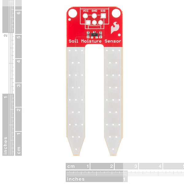
- The enclosure will house a Photon board, a temperature sensor, and a soil moisture sensor.
- The soil moisture sensor will penetrate at least one inch into the soil.
- The enclosure will allow for interaction with two buttons on the top of the board.
- The onboard LED will be visible through the enclosure.
The above features are necessary for a successful design. Notice how the requirements don’t go on to include more specific design decisions such as wall thickness dimensions at this point. In the beginning, keep your requirements as streamlined as possible so you can have flexibility in your design later on.
Pro Tip: Enclosing electronics tends to increase the temperature of the system. You may need to add a fan or some sort of heat rejection method if your components are getting too hot.
Step 2: Model the Internal Components
Now on to the enclosure. I generally start a design such as our plant monitor example by thinking about how the innards will be held.
Ideally, you have a good idea of what’s going inside the enclosure so you can accurately design around it. In our case, we have a Photon Particle board, a temperature sensor, and a soil moisture sensor.
Modeling the larger parts—the Photon board and the soil moisture sensor—will make the 3D design easier and more relevant. You can often find some sort of dimensional drawing from the manufacturer, if not an actual 3D model.
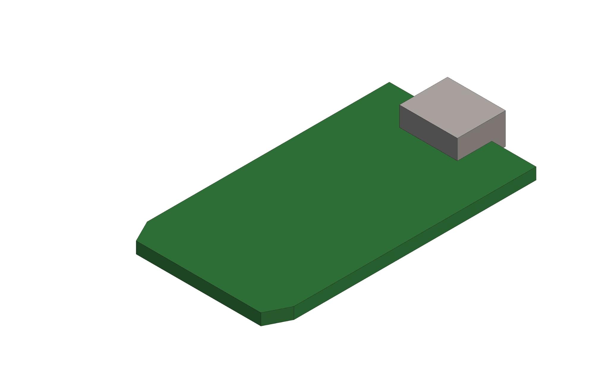
I was able to find dimensions for both the Photon board and the soil moisture sensor, allowing me to create some simple 3D models.
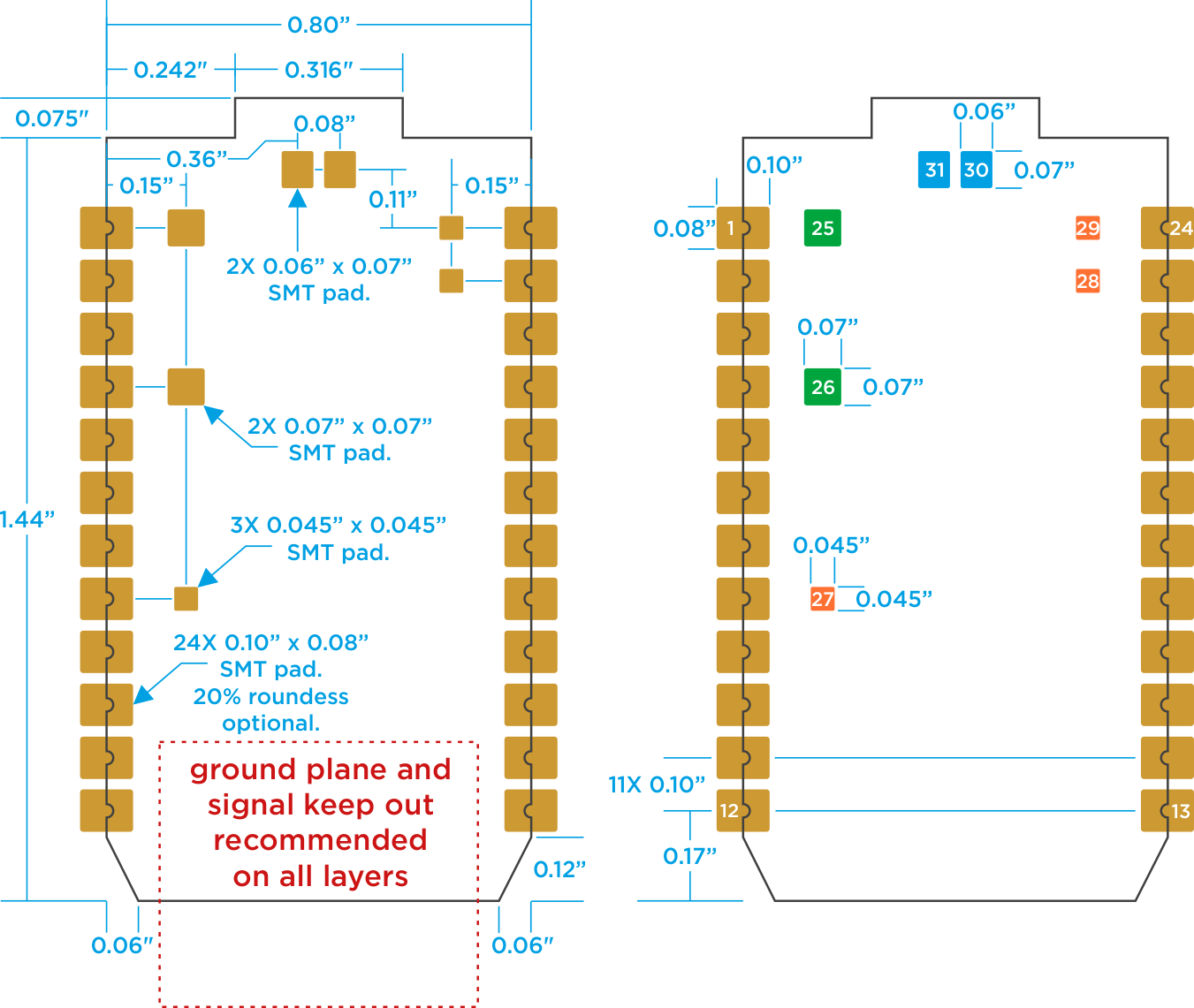
The placeholder models don’t need to reflect every feature of the part. The outer dimensions and any mating features are important to model, but everything else can be left out.
For instance, my models of the soil moisture sensor and Photon board are pretty blocky, but the extents of the parts are accurately represented.

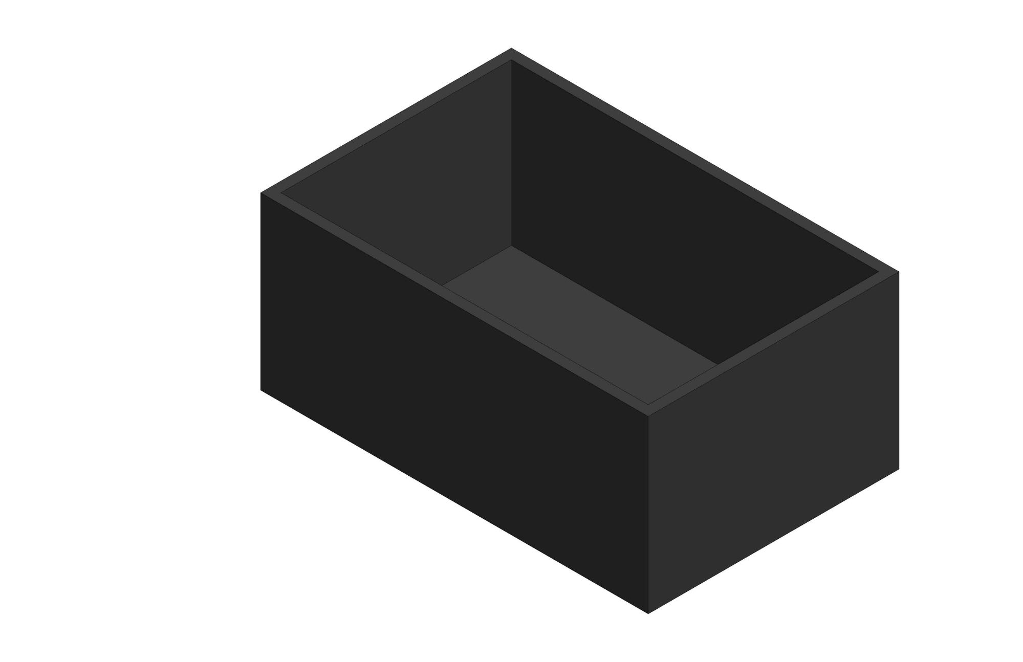
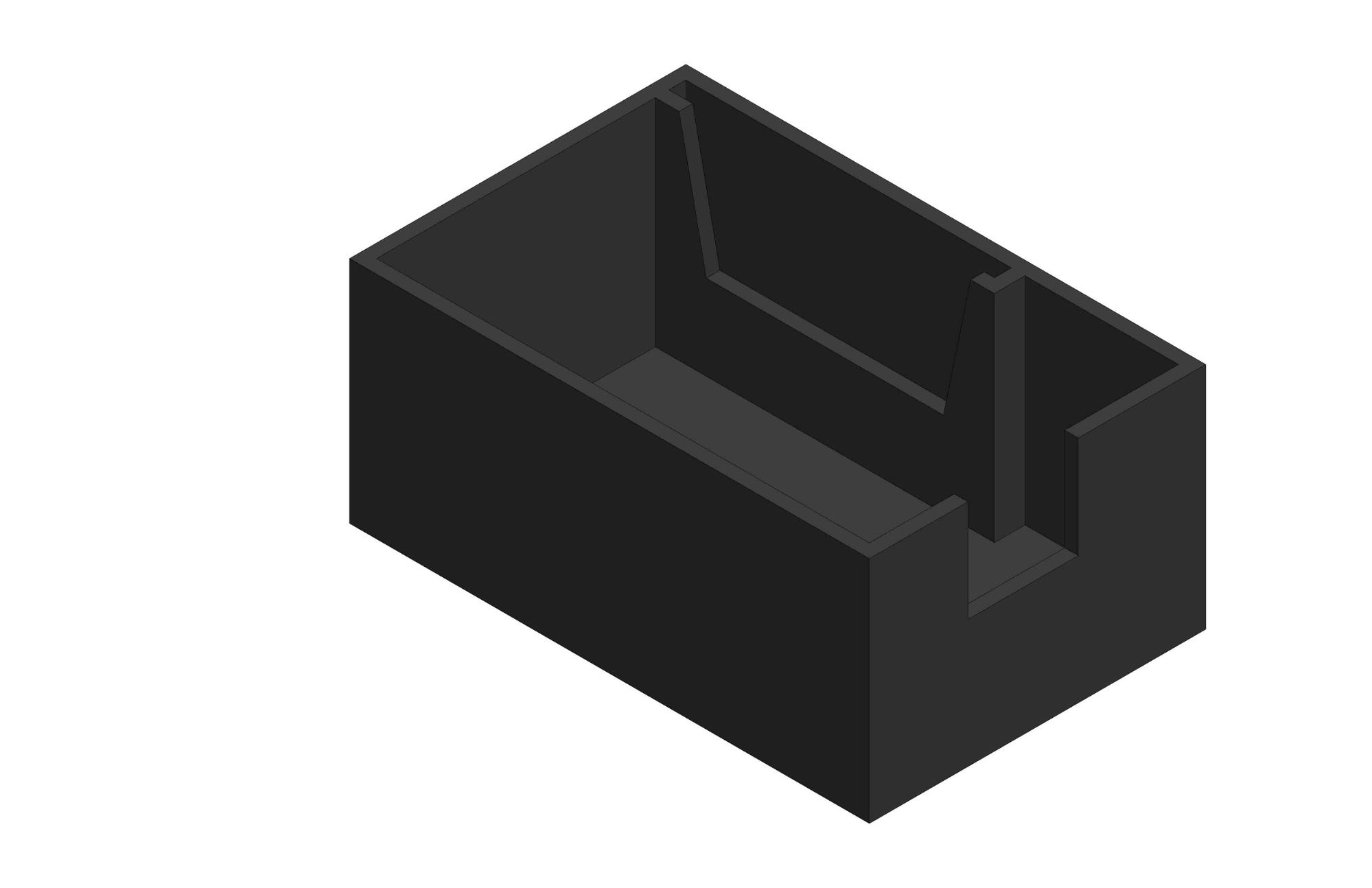
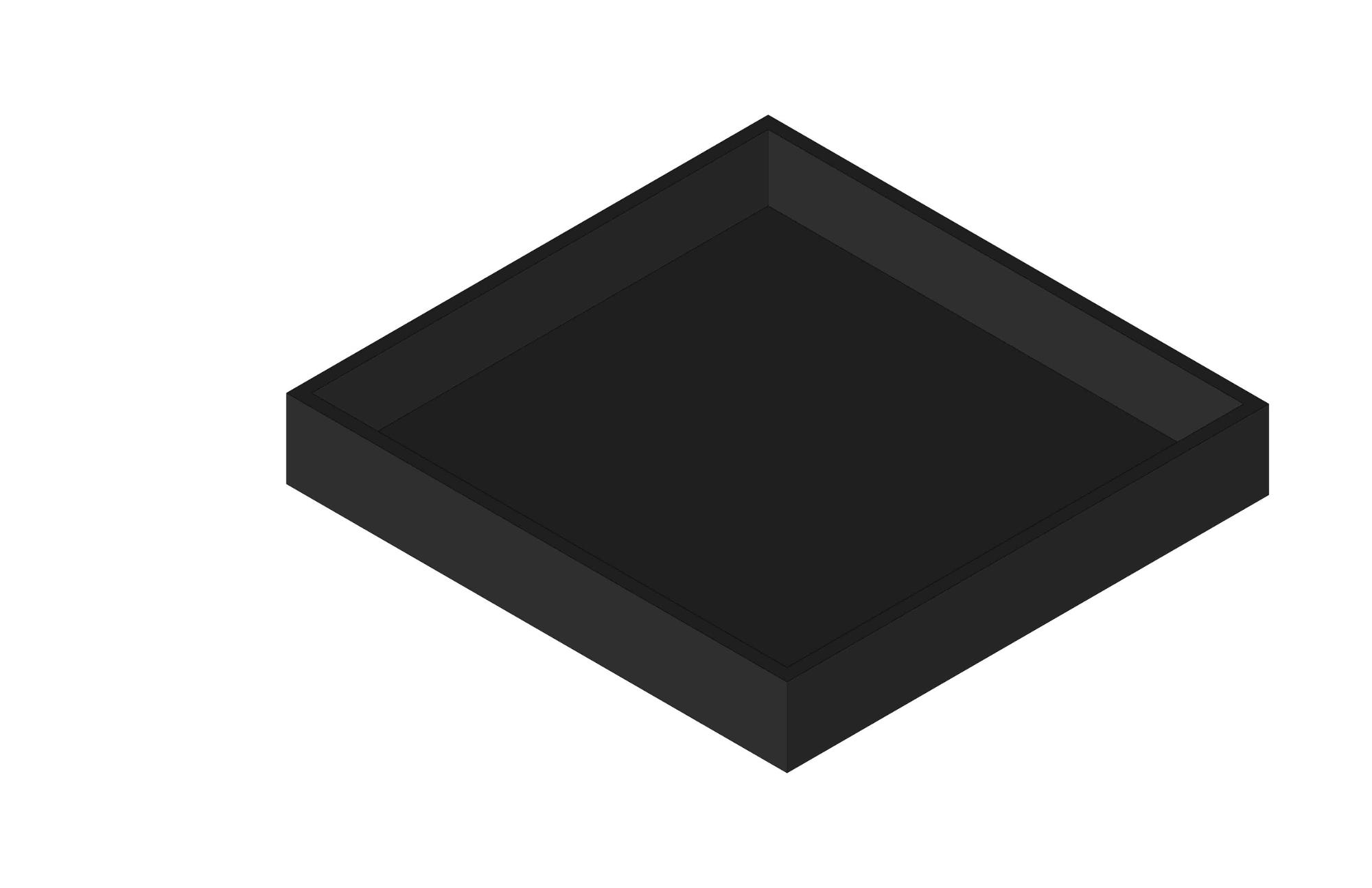
Step 3: Create the Shell
Now that we have models of the electronic parts, we can design our enclosure around them. I start by shelling out a rectangular prism, creating an open box shape.
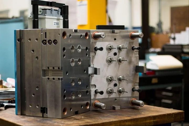
As we create features, we are striving for uniform wall thicknesses because injection molding, the process we’d use for mass manufacturing, requires it.
I’m going to use .040” wall thicknesses because that will be 3D printable as well as injection moldable.
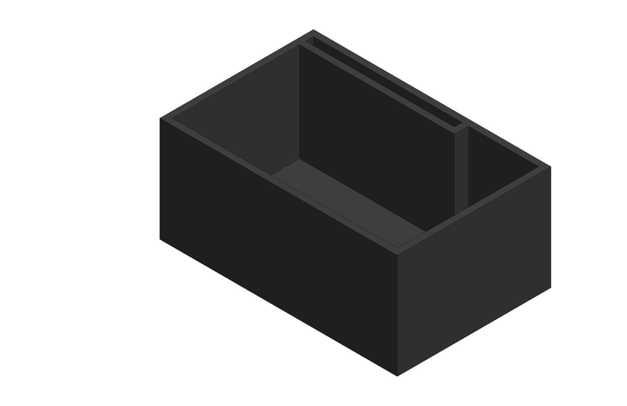
Step 4: Add Slot and External Holes for Soil Moisture Sensor
One of our requirements states that the soil moisture sensor must be inserted at least an inch into the soil. One option is to just run wires from the board to the sensor outside of the enclosure, but I like the idea of a fully packaged product.
I’m going to add a slot that will hold the moisture sensor vertically, allowing the probes to pass through the bottom of the enclosure.
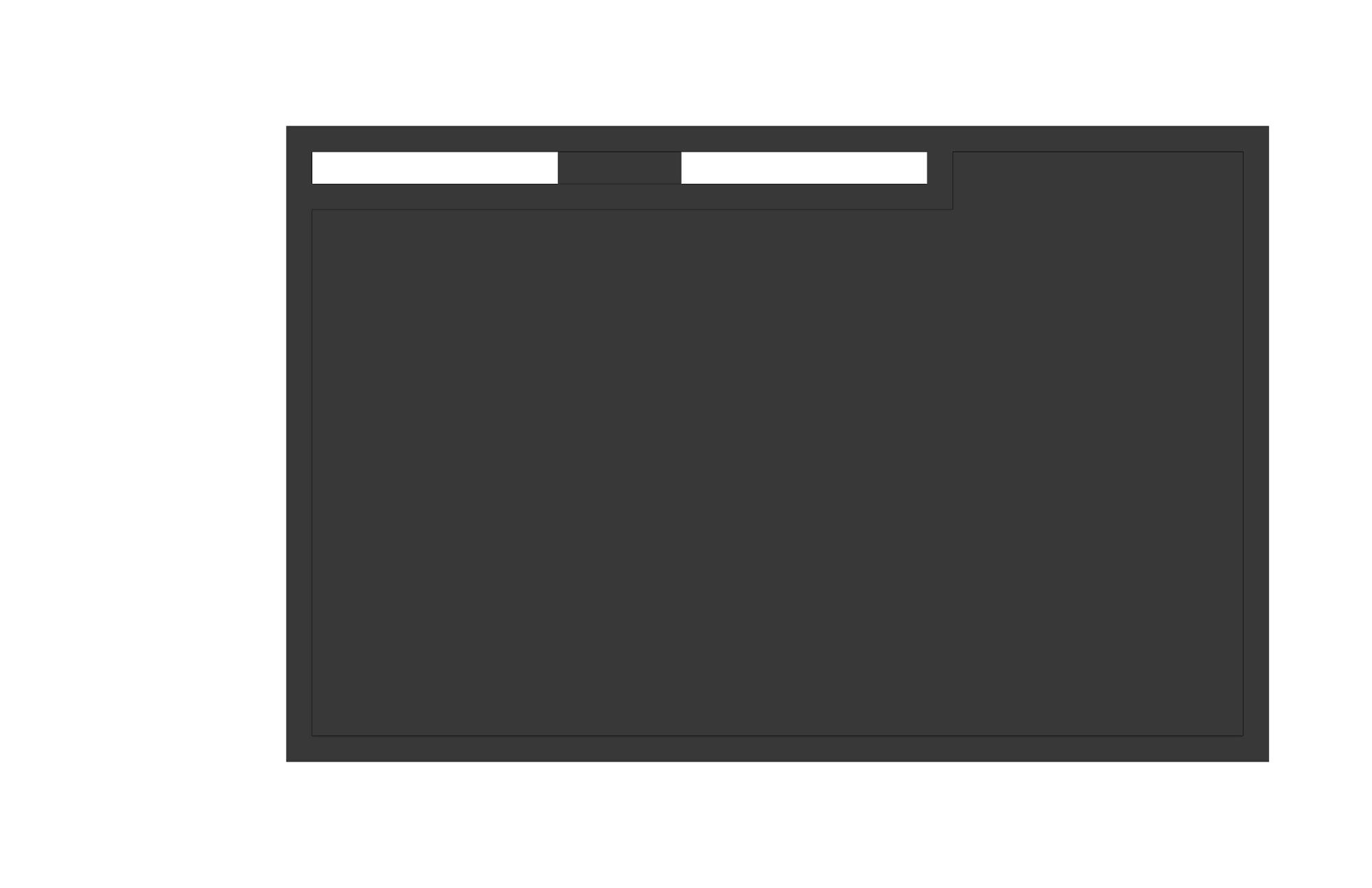
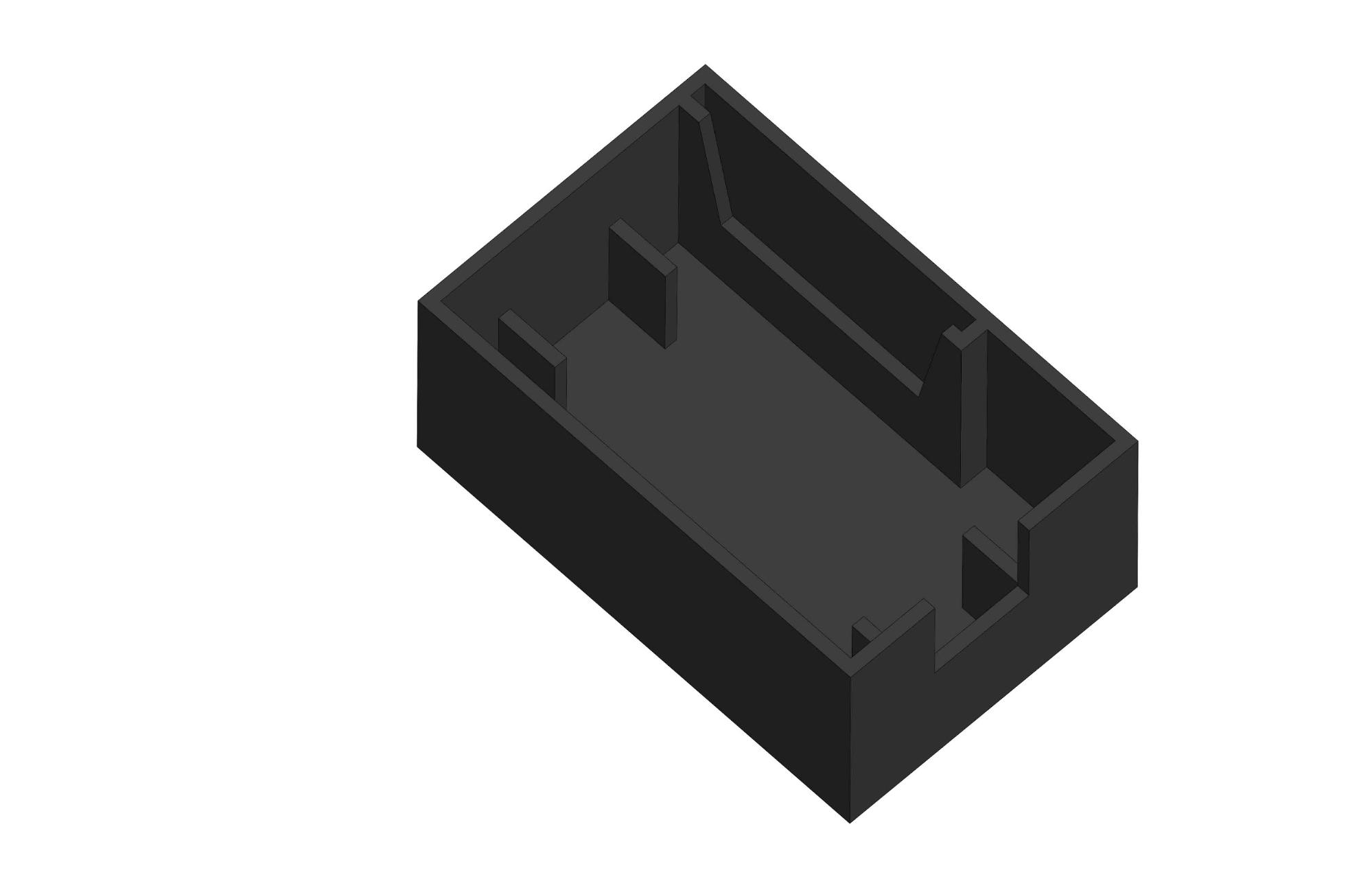
Step 5: Create Cutouts for Wire Connections and Micro-USB Connector
We need to leave room for the wires to be soldered on the top of the moisture sensor, so let’s remove some material while still maintaining a slot.
I’ll also add a cutout for the micro-usb connector. The board will rest with the connector inside this slot, providing some alignment.
Step 6: Create Support Ribs for the Photon Board
The Photon board is currently being held on one side by its micro-USB connector, but we should add supports on which the board can sit.
Luckily, there is nothing mounted on the bottom of the Photon board, so we don’t have to worry about hitting anything. A pretty simple way to create supports is to add ribs of our uniform thickness, where the board can rest.
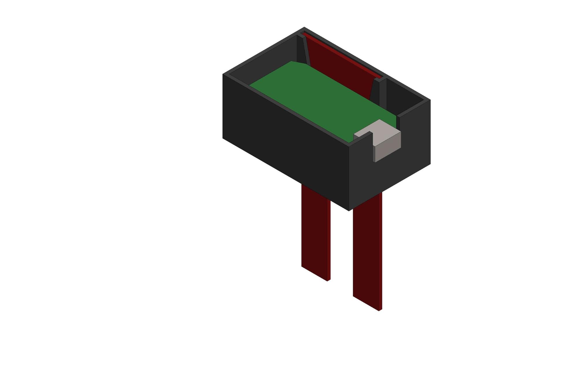
Here’s a current view of the assembly so far:
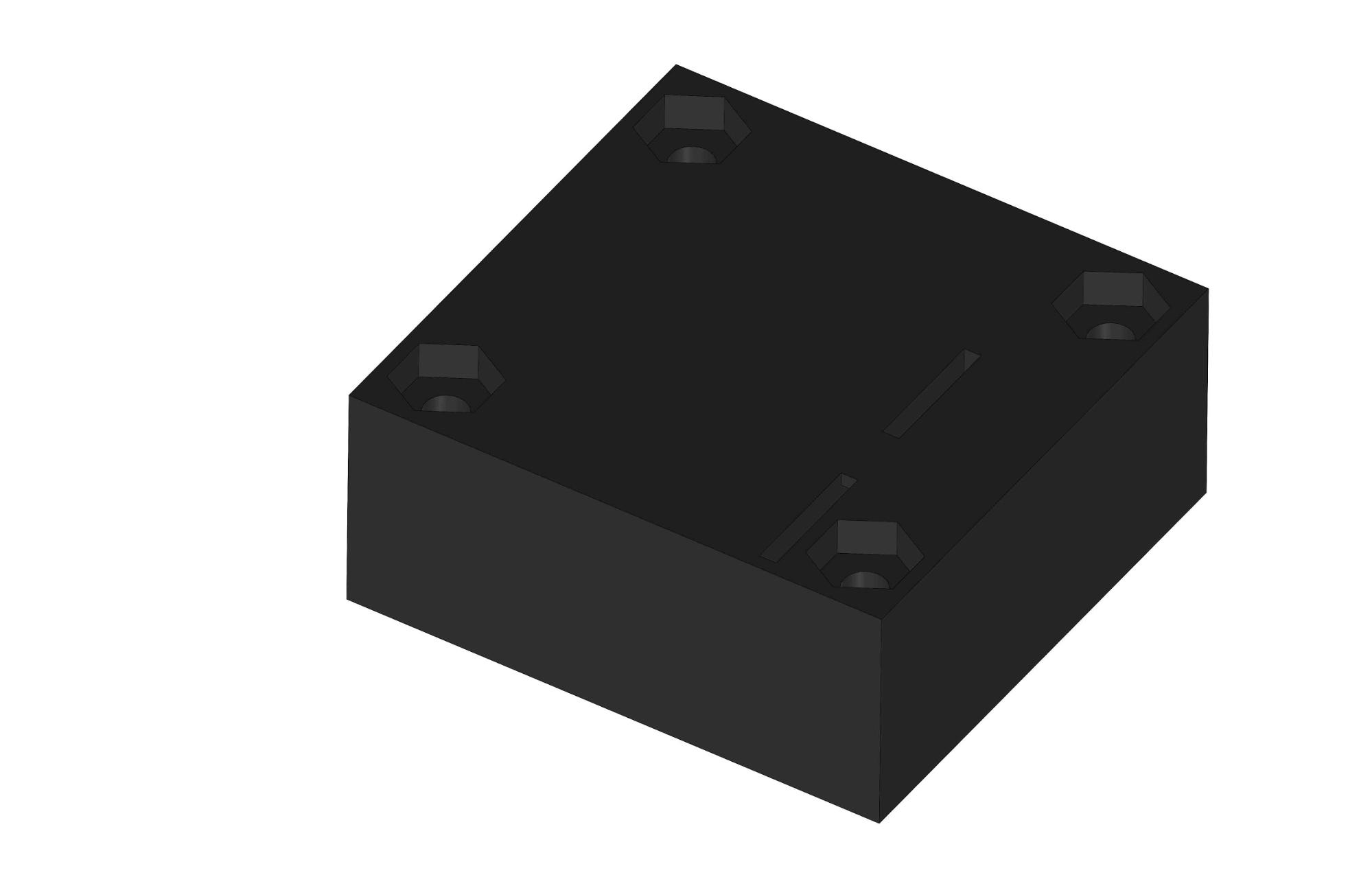
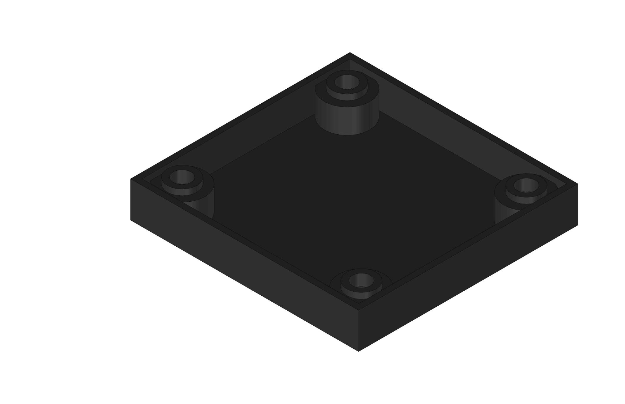
Step 7: Add Lid Fastener Features
Now we need to think about how the lid will be attached. I’m a big fan of the socket head cap screw, so let’s add some extra features around the outside of the enclosure to allow a fastener to pass through.
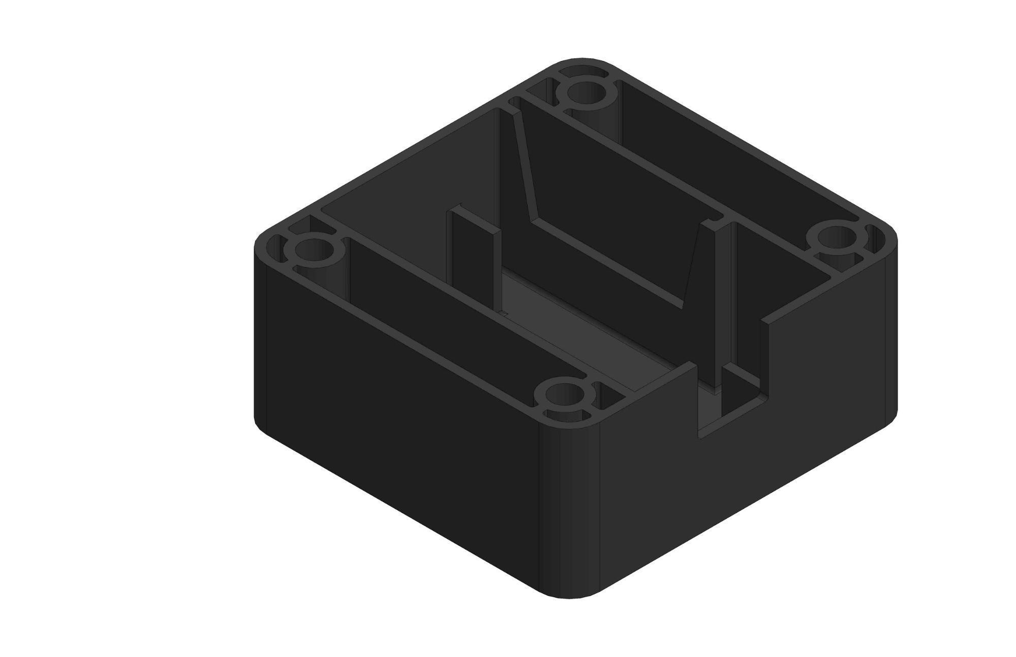
The features you see here are typical in injection molding. Bosses surround the fastener holes and have additional ribs to the outer structure for support. All geometry has our same uniform thickness of .040”.
Step 8: Add Nut Features
A trick for using metal fasteners in plastic parts is to countersink, or cut, the exact size of the nut on the bottom side of the part, keeping it from rotating while you screw in the fastener.
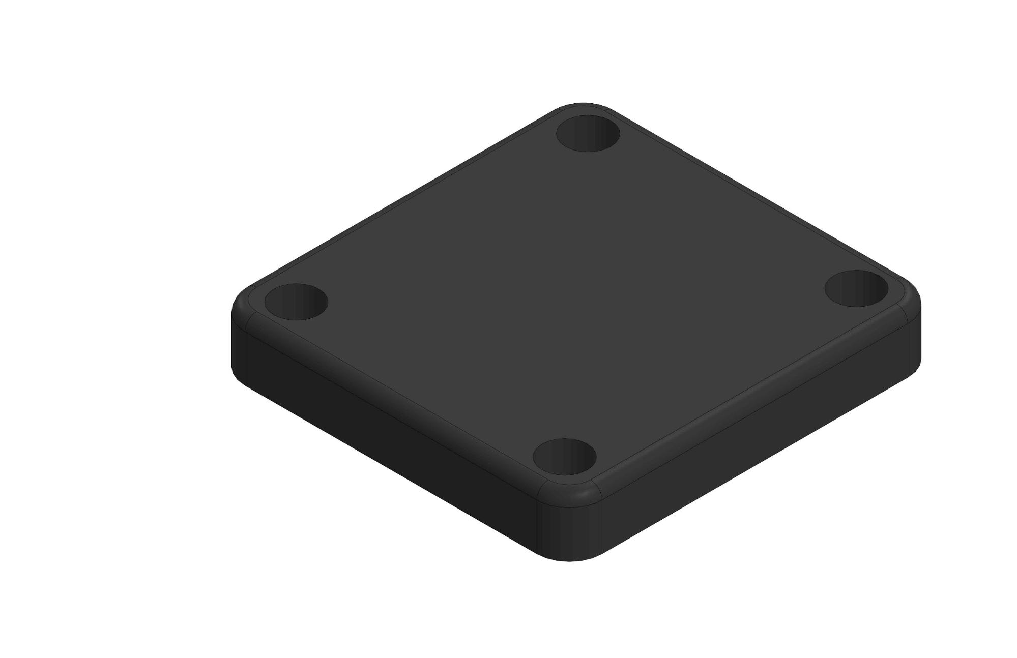
Step 9: Fillet Outer Corners
Finally, we’re going to radius the outer corners, which will decrease the stress concentration there and also make the enclosure look a little more friendly.
We are still keeping a uniform thickness, so for the outer corners the outer radius (0.140”) will be slightly larger than the inner radius (0.100”).
While we’re at it, let’s radius our internal corners, too. It’s important to keep these small to avoid adding too much material and increasing wall thickness.

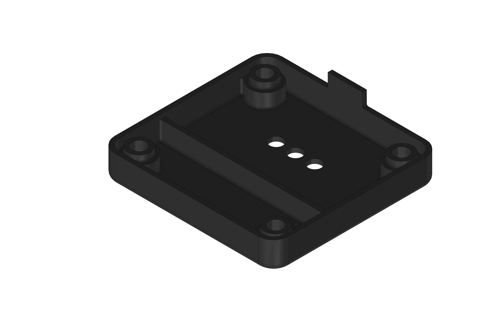
Here is the completed bottom half of our enclosure:
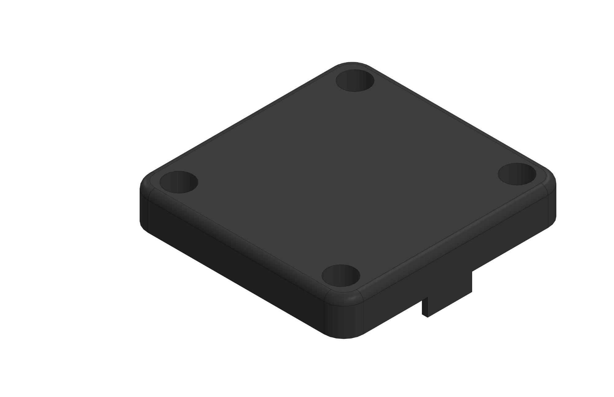
Step 10: Lid Design
Now on to the lid! We’ll use the same types of features in the lid, shelling a box, adding bosses for the fasteners to pass through, countersinking the fasteners into the top, and radiusing the outer corners to match the bottom.
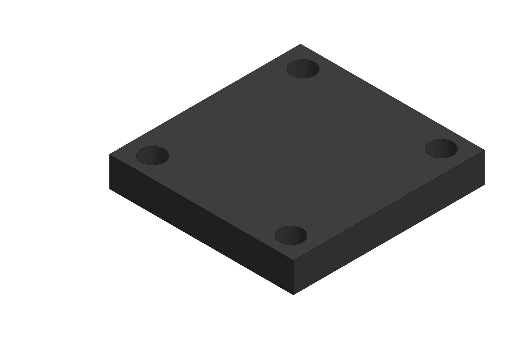
The bosses for the fasteners look as they do above because we are maintaining our uniform wall thickness, and that’s what a countersink looks like from the other side.
I’ve also made the bosses slightly shorter than the outer wall height so that there are no interferences.
Step 11: Fillet Corners and Top Edge
Just like in Step 9 for the bottom of the enclosure, we will radius the outer corners of the lid to decrease the stress concentration and make the lid match the bottom.
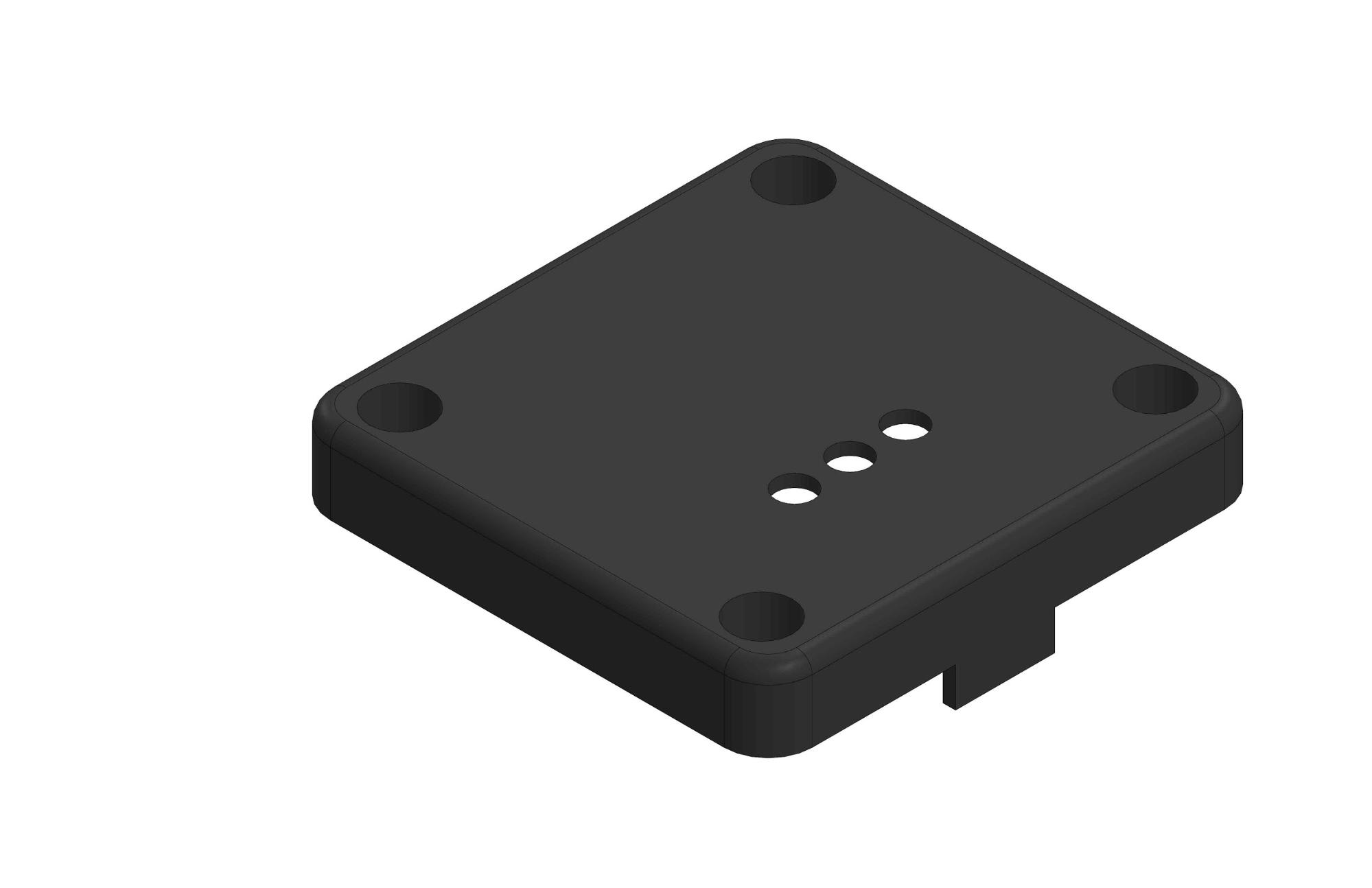
Step 12: Add Protrusion to Hold Top of Micro-USB Connector
This little boss will mate with the top of the micro-USB connector, securing it in the slot in the bottom of the enclosure.
Step 13: Cut Holes for Buttons and LED Light
As per our requirements, holes are created for interacting with the buttons on the board and seeing the LED light.
Step 14: Add Rib for Holding Moisture Sensor
While the moisture sensor is being pushed into the soil, it will probably come up to contact the lid, which is less than ideal.
To remedy this, I’ll add a rib that will hold the moisture sensor down in a more secure position.

Step 15: Radius Internal Corners
The final step is to radius all of those sharp corners that are not only aesthetically unpleasant, but have large stress concentrations. Again, we’re going to keep the radii small (.005”) to avoid adding too much material.
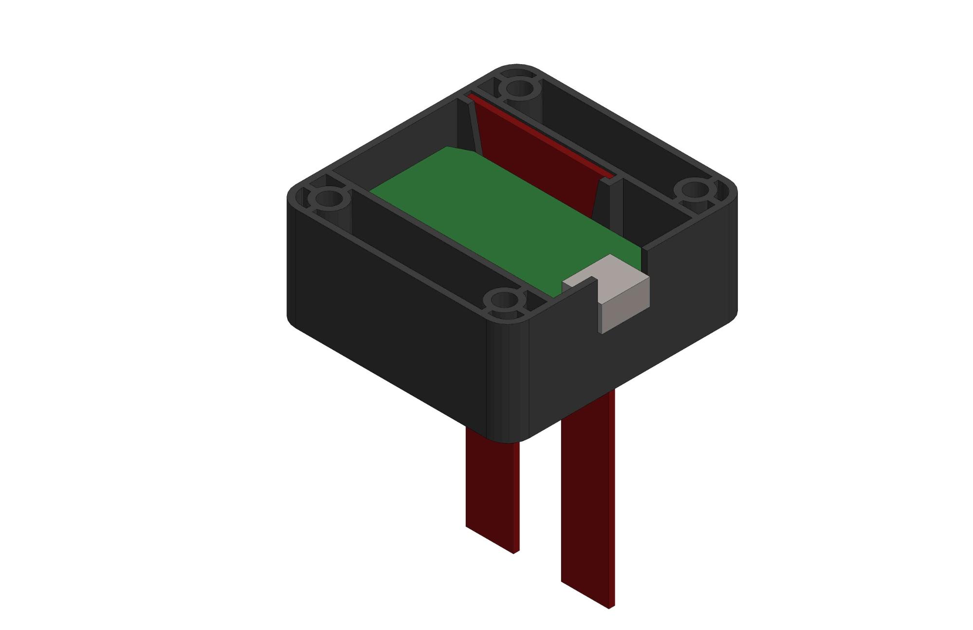
Now let’s add the lid to our full assembly and throw in some hardware.


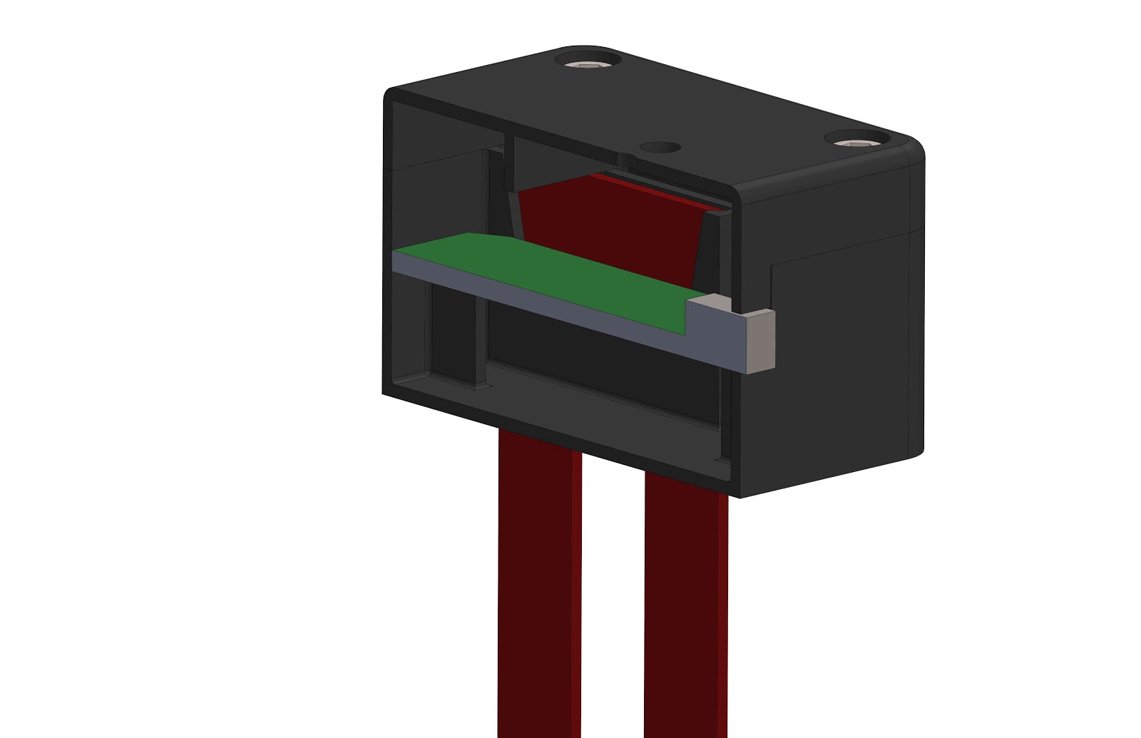
Be sure to leave space for wires and their bends! It’s easy to forget about wire routing while you’re designing until you’re trying to assemble the product. You can see from the above section view that I’ve left plenty of room (nearly half an inch) above the board for wires and the small temperature sensor.
Final Notes
Hopefully this gives you some helpful guidelines for designing and prototyping your own product enclosure. To start 3D printing your enclosure design, hop on over to Fictiv where you can get 3D printed parts delivered in 24 hours.
For more detail on enclosure design features, check out our posts on how to design snap fit components, choosing the best fasteners for 3D printed parts, how to conduct a tolerance analysis for 3D printed parts, and how to design light pipes.