Time to read: 8 min
Once you have modeled your parts in CAD software, you may be tempted to send them off to be manufactured in your 3D printer. However, before doing so you should perform a tolerance analysis to make sure what you’re printing “stacks up.” Tolerance Analysis, or tolerance stack-up as it is sometimes known, is a critical part of the high-level analysis of 3D printing or prep work to do before any other manufacturing process, like CNC machining. You especially want to perform a tolerance stack-up when designing moving parts, parts under pressure, or anything that needs to mesh and fit up perfectly.
Deviations between the nominal size you see on the screen and the printed size occur for several reasons. Whether it be filament or resin, certain materials have a slightly different printed dimension due to thermal expansion and contraction. Layer thickness, nozzle size, and final build size dimensions all have an impact on how parts interact and fit together. Conducting a tolerance analysis helps avoid printing and assembly errors and saves the cost of wasted printing material and time printing parts that don’t fit.
Download our free tolerance analysis calculator here
Here’s a visual example of how a stack-up analysis can be used.
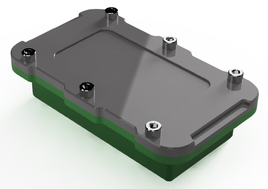
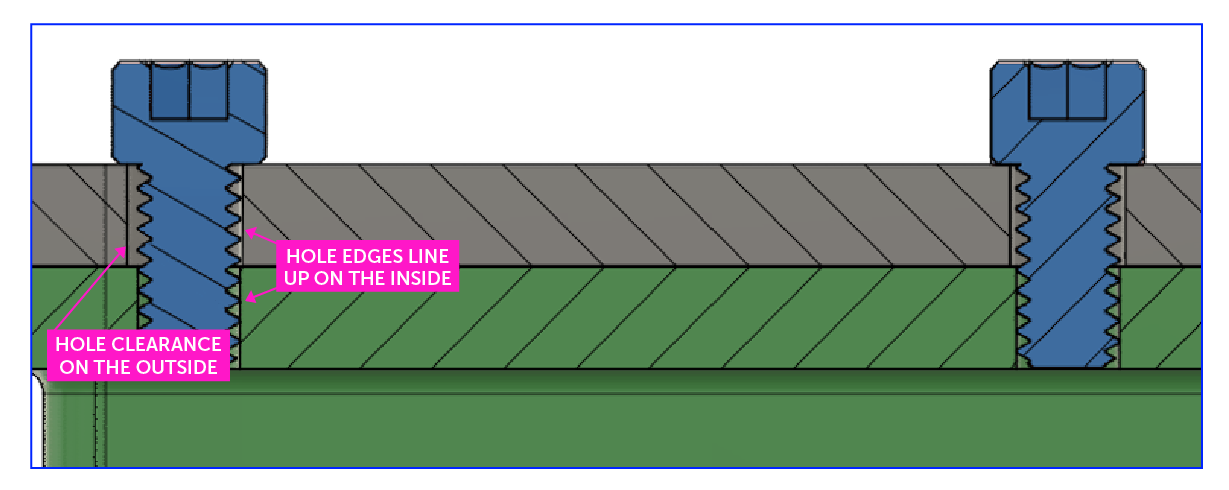
This assembly consists of a lid, fastened to a base by six (6) ¼-inch socket head cap screws. The screws not only have to pass through the lid to fasten to the base but also line up so the rest of the screws do the same. In this example, a 0.250” inch screw must go through a hole slightly larger than 0.251”. Some tolerance needs to be added because the manufacturing process will not result in a perfect 1:1 match with our CAD model. But what happens if we have too much leeway, say 0.030” of error to the outside screw holes?
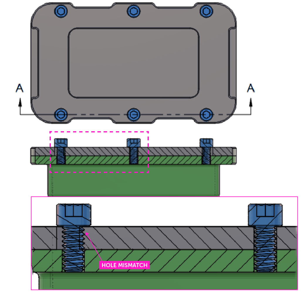
The middle screw fits, but the added tolerance creates a mismatch between the outside screws which will not be able to pass through both the lid and base, causing a misalignment.
With this in mind, there are several methods to conduct a tolerance stack-up analysis for 3D printed plastic parts. The two general methods are statistical tolerance analysis and worst-case scenario analysis.
Statistical Tolerance Analysis
3D Analysis with CAD Software
In 2022, CAD software either comes pre-loaded with or has the option to add in a tolerance stacking feature. In Solidworks, tolerance analysis is carried out in Geometric Dimensioning and Tolerancing applications — DimXpert to apply dimensions, and TolAnalyst, a more powerful tool that interfaces with DimXpert. The TolAnalyst add-in assesses minimum and maximum tolerances automatically through root-sum-squared (RSS) tolerance stack-up calculations between different selected points on the geometry.
RSS Tolerance stack-ups assume that a certain number of parts will fall within acceptable standard deviation ranges. These parameters are typically set on an Excel spreadsheet, that lays out the target rates of rejected parts that will come out of a batch of manufactured parts and the minimum nominal dimensions necessary for that outcome.
For a Monte Carlo analysis, you can also obtain similar results because it works off a probability density function (PDF) that can accurately simulate the necessary values. These are normal or Gaussian distributions that better represent random variables versus more uniform functions. Both RSS and Monte Carlo analyses assume you are working with a more relaxed range of tolerances consistent and more efficient for higher volume production.
Worst Case Tolerance Analysis
Worst-case scenario calculations are typically used in prototype manufacturing because they result in higher precision in the manufacturing process.
Positional Tolerance Analysis
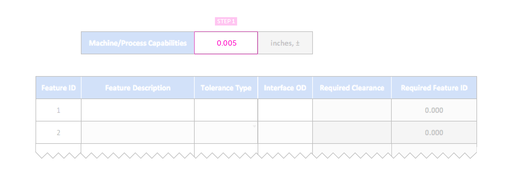
To demonstrate a Positional Tolerance analysis, let’s use the container, lid, and screws model from earlier and use Fictiv’s free tolerance analysis calculator, which has tabs where you can follow along for both positional and linear tolerance. Download the analysis calculator and follow the next step-by-step instructions for determining required clearances and feature IDs. The spreadsheet will look like this when you download it:
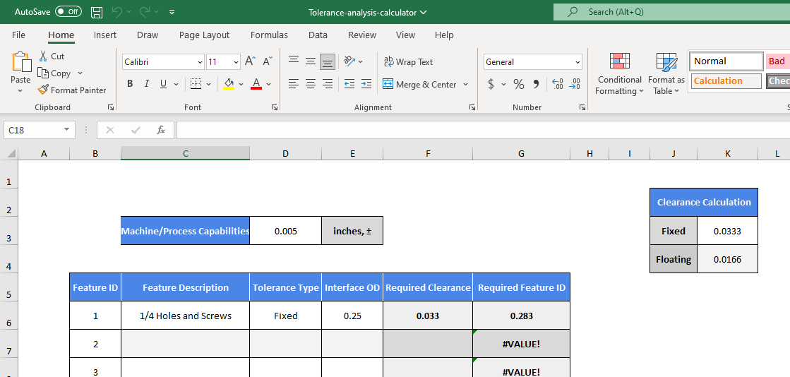
Step 1 – Machine Capabilities
First off, we need to know our machine’s capabilities. Let’s say we’re using Stratasys Fortus 450mc FDM printer, which has a dimensional accuracy at ±.005” or ±.0015 in/in, whichever is greater. We will use ±.005” for our example. Input this value into the Machine/Process Capabilities cell as shown below:
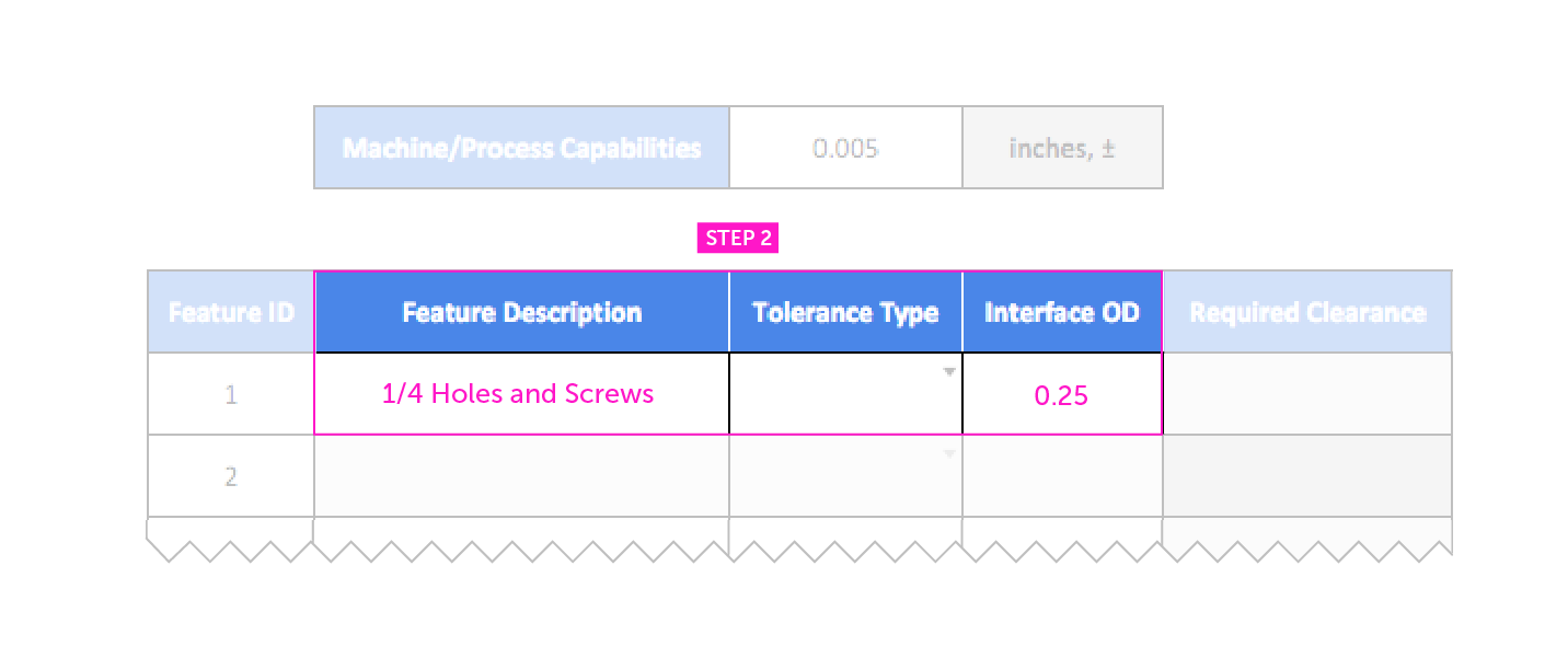
Step 2 – Input Components and Dimensions
Next, we input our parts, features, and interface dimensions — which in this case are our ¼-inch holes and screws. For interface OD (outer diameter), input the maximum size of the screw, not the hole. For our example, we will use 0.25.
Step 3 – Calculate Clearance
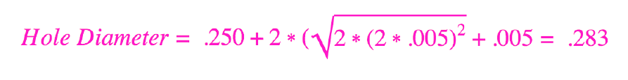
Here’s where the calculations come in. Depending on what type of part you are using, the formula may vary; always confirm you are utilizing the latest version of ASME Y14.5 Geometric Dimension and Tolerancing standard. For our example, we’re using a modified formula based on a “fixed fastener case” to better interface with our printer’s tolerance:

This resembles a trigonometric principle, where if the axes of the holes are displaced relative to each other at the maximums of each tolerance, then the displacement will be equal to the hypotenuse of a right triangle with a side equal to 0.010”. A tolerance zone of ±.005” and the hypotenuse measured will look like this:
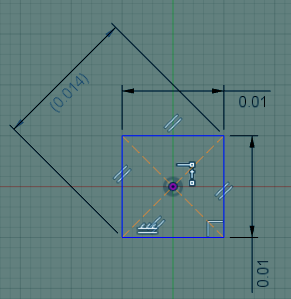
Multiplying 0.005” by 2 gives us 0.010”, which is why the sides are 0.010”. The reason the hypotenuse is doubled is due to needing twice the increase in clearance of diameter for displacement between hole axes. The tolerance is factored back into the formula and looks like this:
Using our Excel calculator makes it a whole lot easier to plug and play, rather than making calculations for every item. Now, the tolerance type comes into play; because our screws are threaded and fixed into place, we should select a fixed tolerance type in the drop-down selection.
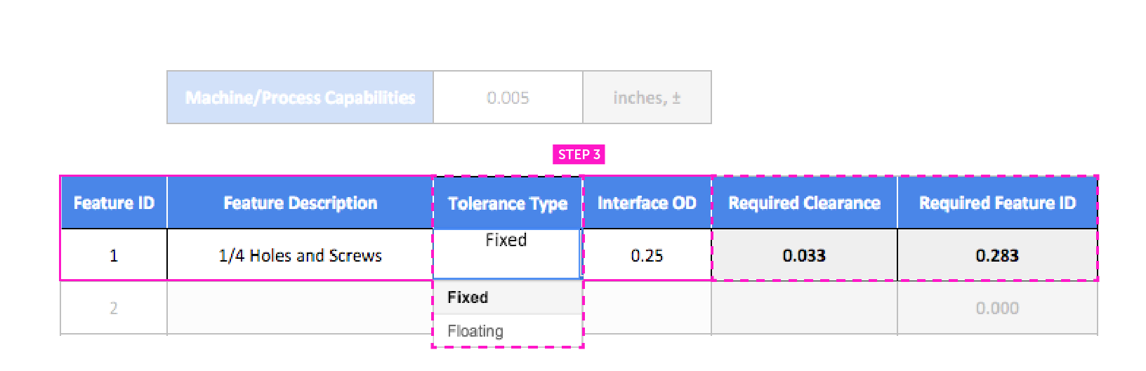
If we were using a fastener and nut instead of directly threading the parts, we would choose a floating tolerance. This cuts the necessary clearance in half and expands the holes by the same amount. You can change the tolerance type to see how it affects other parts.
Step 4 – Adjust the CAD Model to Accommodate the Tolerance
With our numbers in, we can edit our design to correspond with the tolerance analysis we just conducted. This ensures that the parts printed out the first time will fit accordingly and no reprints or edits will have to be done later on.
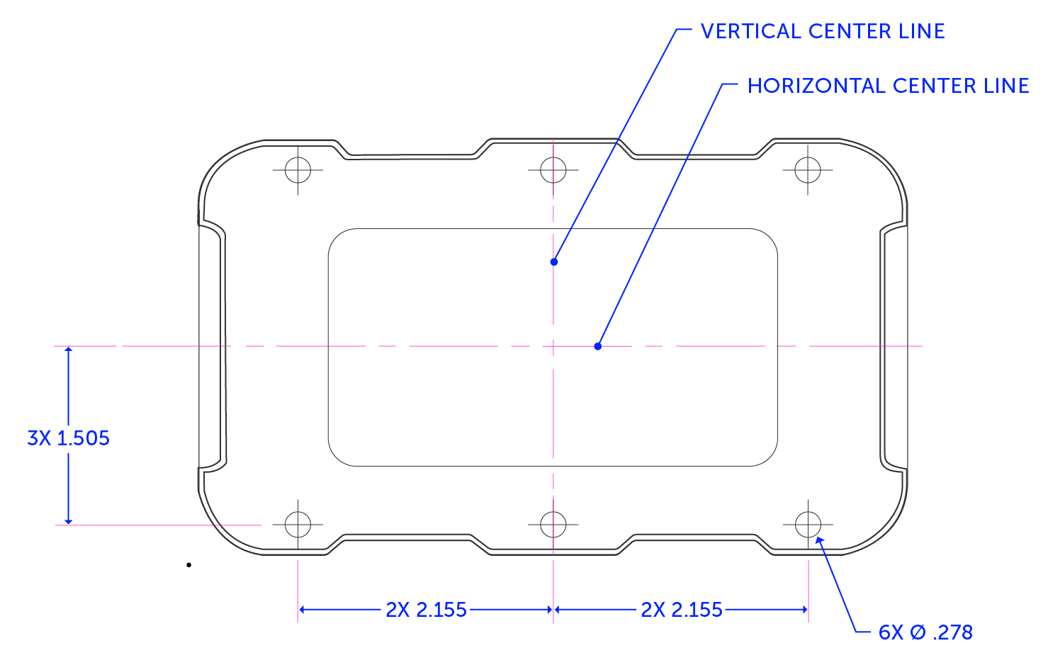
These are what the nominal dimensions and tolerance look like for the hole size and spacing we have calculated:

The models for both the lid and the base have the holes spaced at 2.150” and 1.500” from the center planes of the part, while the through holes in the lid will be modeled to a diameter of 0.283”.
But at the extremes of our tolerance zones, parts can also appear to be printed like this when you measure them:
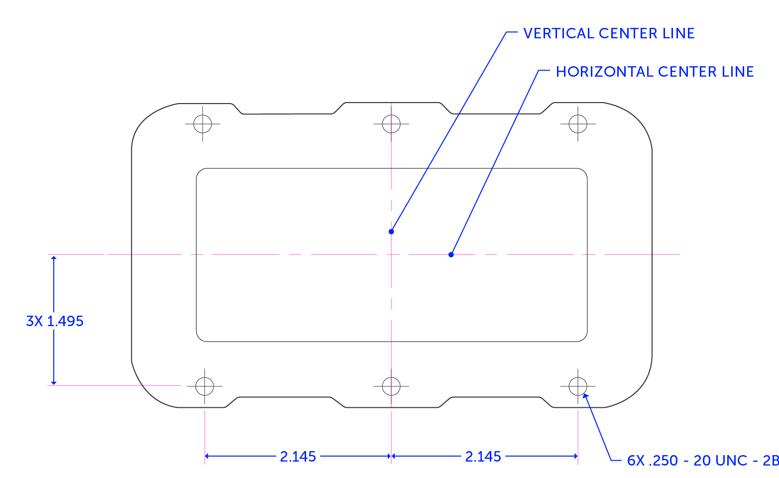
This is what both the lid and base would look like if they were produced at the two opposite ends of their allowed tolerance bands. Even in this worst-case scenario, given the machine’s accuracy, we will still have a reasonable fit between the lid, base, and screws.
Note that these are still extremes after doing our tolerance stack-up. Without a stack-up, there is a higher chance of more mismatches where parts will not line up. After conducting our tolerance analysis, we are within a given means of accuracy and can expect everything to fit together.
Linear Tolerance Analysis
For our linear tolerance analysis, we follow the same foundation as with the positional tolerance analysis. For this example, we are designing a plug into a socket, and using a machine accuracy tolerance of ±.005”. This is what it looks like:
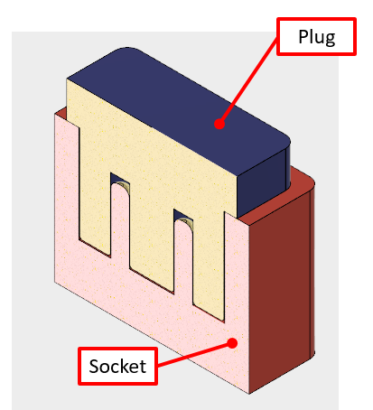
For the plug to not contact the bottom valleys of the socket, we need to make sure the shoulder lines up with the top. Here’s a target example of what we are looking for.
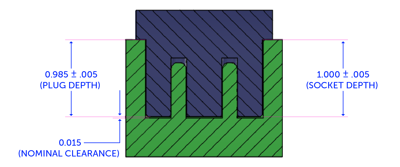
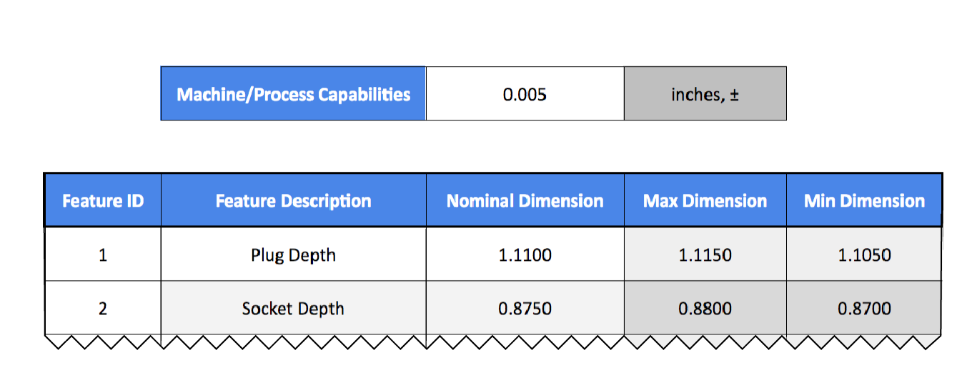
Let’s go back to our Excel spreadsheet in the linear tab and plug in the dimensions as follows. Use the second tab, named Linear, of the spreadsheet. Remember, our machine/process capabilities are still a constant of 0.005± inches. You can see the dimensions for the features plugged in and the resulting, calculated max and min dimensions.
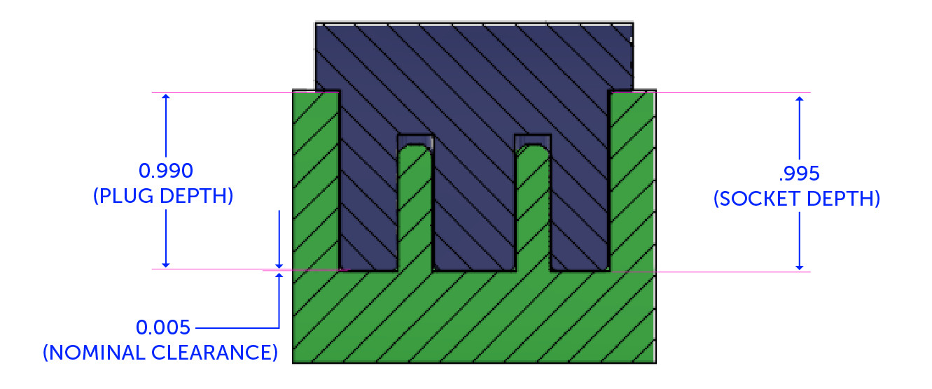
In a perfect world, everything would match up perfectly from CAD to manufactured parts, and we would end up with a nominal dimension of 0.015” of clearance every time. In reality, we could have a gap as low as 0.005” at the extremes of our tolerances. Using the spreadsheet, we can calculate clearance by subtracting our max plug depth of 0.990” from the depth of 0.995”.
Everything matches up so far, but what if we add other variables into the mix, like a faceplate between the socket and housing? Now, tolerances can vary even further.
We still have the same nominal clearance from before, but there is now twice the number of opportunities for tolerances to stack up unfavorably. Adding two tolerance interfaces of 0.005” adds 0.010” of tolerance stack. Now, instead of 0.015” of clearance, there is a worst-case scenario of 0.005 interference, and these are what the measurements will look like:
And here’s what the dimensions will add up to:
When we subtract the maximum plug length from the sum of the minimum dimensions of all the features, it adds up like this:
Clearance (+)/Interference(-) = .870 + .120 + .120 – 1.115 = -.005
We know it interferes because it is a negative value rather than a positive value (which indicates a level of clearance). So, to keep the design the same while still having 0.005” of clearance, we will add an extra 0.010” to our nominal dimensions, to get a clearance gap of 0.025”.
Final Tips and Tricks
1. If you can not open tolerances to ensure a 100% fit based on machine capabilities, or just don’t want to tinker with the CAD dimensions, you can still reduce the clearance in the clean up stage through sanding, Dremel, or similar tools.
2. In tolerance stacking, the fewer moving parts that interface with each other, the better.
3. The smaller a piece gets, the tighter the tolerance will be. Limit the size of components based on the machine you are using — for example, PolyJet printing prints at finer resolutions versus FDM printing. We recommend you weigh the pros and cons of both between your acceptable cost and time.
The more you tinker with tolerance stacking, the better you will be able to understand risks and analyze the limits you can test between different materials and machines. Practice makes perfect! As printing technology advances, so too will the tools used to make the job easier. Try out our free tolerance analysis calculator, and check out Fictiv’s 3D printing and CNC machining services for your next manufacturing or prototyping project!