Time to read: 7 min
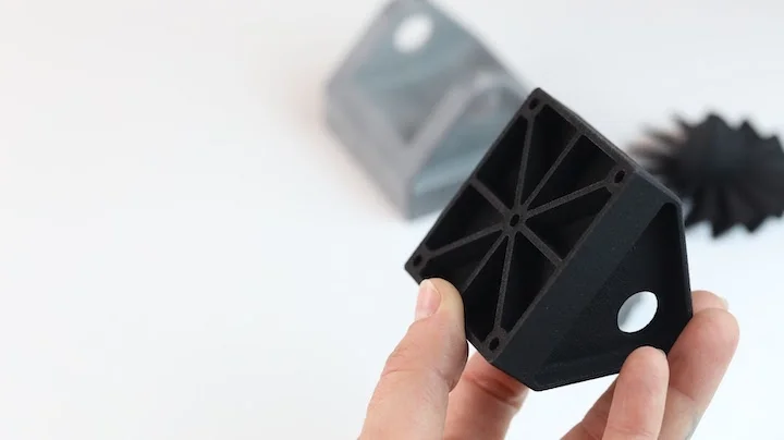
When designing plastic components, it’s often necessary to add ribs and gussets to improve the stiffness and strength of load-bearing features. This reduces material volume and optimizes print time for 3D printed parts, since it takes longer to make these features solid structures (print time is largely driven by the volume of material for a specific component). Plus, if you’re using 3D printing to prototype prior to injection molding, adding ribs and gussets will create a plastic part that’s a closer representation of an injection molded part for mass production.
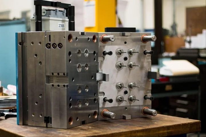
In injection molding, ribs and gussets are used so that designers can avoid using walls that are too thick and that take longer to cool, or that are non-uniform and cool inconsistently. A variety of defects, such as shrinkage and warping, can occur if the features on injection molded parts are too thick.
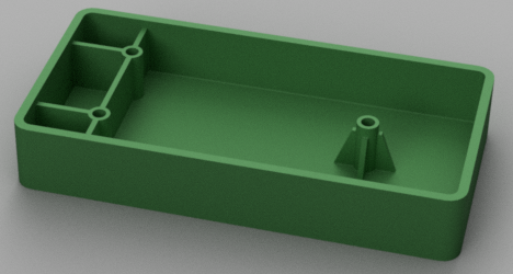
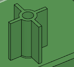
The image below features ribs on the left bosses and four gussets on the boss on the right:
In this article, I will quantify the structural benefits of adding gussets vs ribs to your 3D printed part designs using FEA studies, then walk you through the best practices for proper application of these features to plastic prototypes.
Quantifying the Structural Benefits of Gussets and Ribs
Ribs and gussets seem like small features, but the FEA (Finite Element Analysis) studies below demonstrate their structureal importance.
Gussets
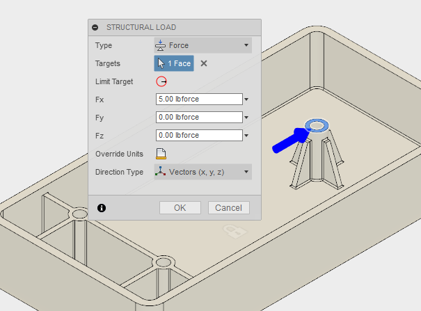
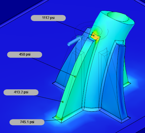
The image below depicts a five lbf (pound-force) load on the boss with gussets in order to demonstrate total stress and deflection in the current state. All of these simulations use the material properties of ABS, so they’re consistent with common 3D printing materials.
As you can see below, the majority of the part is stressed to the 400 psi range, with the maximum stress reaching just over 1,200 psi (not shown, as it is on the compressive side). The areas with higher stress concentration are all on the tension side, with the highest tensile stress around 1,100 psi.
In the following images, we can see the same FEA study conducted without the presence of gussets, but with the same loading conditions and boss geometry. The stresses are now more than double what we saw in the prior study — indicating that without gussets, the boss is less than half as strong.
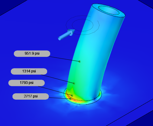
It’s immediately apparent that the feature is not as strong without the gussets. In fact, this feature is now experiencing stresses close to the yield strength of the ABS material we selected (yield strength=2,900 psi).
In addition to the increase in strength, the parts undergo much less deflection when we add gussets. And for applications that require positional alignment or rigidity, this is critical. The side-by-side images below show just how much more the un-gusseted boss deflects.
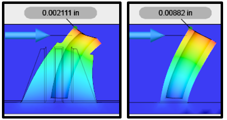
The boss deflects four times as much at the topmost point when it has no gussets, which is a major problem for both function and aesthetics. Gussets do not always have to be angled, however, as they can also be straight features:
Ribs
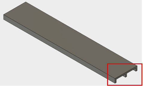
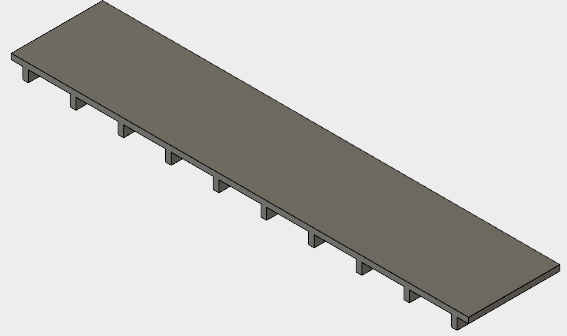
Our next example shows another way we can use structural ribs when not attached to a boss. Let’s start by looking at two different versions of the underside of a shelf:
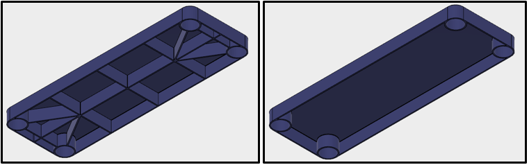
The shelf on the left features added support ribs, while the shelf on the right has all of the ribs removed. After seeing the impact that gussets have on the strength of a boss, its easy to conclude that ribs in mechanical design will add strength and rigidity to the shelf — but can such thin features provide that much support?
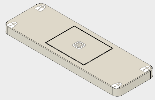
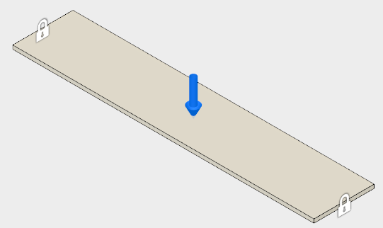
To quantify the benefit of our ribs, we’ll conduct another FEA study. This time, we’ll analyze the impact of a 50 lbf box with base dimensions of approximately 6” x 8”. We’ll use ABS for the shelf material again and simulate the support legs of the shelf by fixing the flat inner circle of the leg supports.
The setup is shown below:
We’ll start out by solving the FEA with the ribs included to locate the high-stress regions. This information will be used to drive our safety factors, as well.
I want to target no less than a 3:1 safety factor for this design since it’s load bearing. The image below details the results of the study:
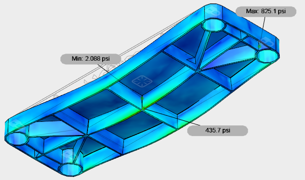
The maximum stress is 825.1 psi, located in the cylindrical slots for the shelf leg insertion during assembly. Given that we’re using ABS with a yield strength of 2,900 PSI, our safety factor is 3.5, which exceeds our requirements.
In the next image, we’ve run the same FEA study on the shelf without the additional support ribs.
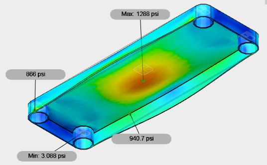
Here, we see the stresses shoot up to a maximum 1,288 PSI, and many other locations within the shelf are stressed to a much higher level, as well. Our safety factor has also been reduced to 2.3, which is well below our requirement.
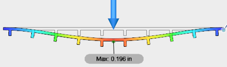
But the safety factor and load rating aren’t the only factors to examine. Excessive deflection is another consideration because a bowed shelf is unattractive and less stable than a flatter shelf. In the image below, the top picture is of the loaded shelf with ribs, and the bottom picture is of the shelf without the additional ribs.
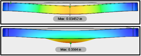
We can see that not only is the maximum displacement an order of magnitude higher in the shelf without ribs, but the center of the shelf sags significantly. These illustrations are exaggerated to detail the direction of deflection, but 0.35” is an unacceptable amount of deflection, in any case.
Here’s a quick comparison table to recap the results of ribs vs no ribs on the shelf:
| Geometry | Max Stress (PSI) | Factor of Safety | Max Deflection (inch) |
| Shelf with ribs | 825.1 | 3.5 | 0.03452 |
| Shelf without ribs | 1,288 | 2.3 | 0.3564 |
All the results clearly show the added benefit that ribs have on the stresses experienced by the shelf, its maximum deflection, and Factory of Safety.
The Proper Application of Ribs
Now that we’re clear on the importance and benefits of ribs, it’s important to understand their proper application — ribs added in the wrong direction or orientation are often useless.
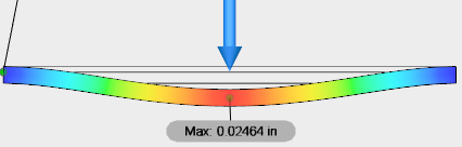
To demonstrate, let’s look at a flat plate supported on both ends as shown below, with a ten lbf load placed in the middle.
After performing the FEA, we see quite a bit of deflection under such a low load.
So, we know we need ribs, but what is the best rib placement?
At this point do we just start throwing lines and extrusions on the part at random? Not quite. Mathematically, it’s best to add rib height in the direction of loading, so that means if we’re looking at the part from the front, as shown above, we want the part to look taller from the addition of ribs.
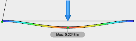
In the image below, I’ve added three ribs that are 0.25” tall.
It’s time to run another FEA. The image below is of the same FEA study as above, but with our newly added ribs:
We’ve cut our total deflection down by almost an order of magnitude again, simply by adding three small ribs!
Now, let’s look at the wrong way to add ribs. In our previous example, the ribs all connected to support features and increased height in the direction of loading. Now let’s investigate what happens if we change the direction of the ribs 90 degrees:
Yet again, we turn to our trusty FEA study to see what happens when we place the same load on this component:
Now, we get little to no benefit from the ribs because they don’t connect to any of the support features.
The deflection is barely less than our original FEA with no ribs at all. If the shelf were fixed on the front face, these ribs would help, but here the shelf is only supported on the left and right ends. The lesson? Again, ribs placed perpendicular to the supports provides a far greater reduction to maximum deflection.
Design Guidelines for 3D Printed Ribs & Gussets
Ready to test physical prototypes of your designs? The design guidelines for 3D printed parts are relatively simple:
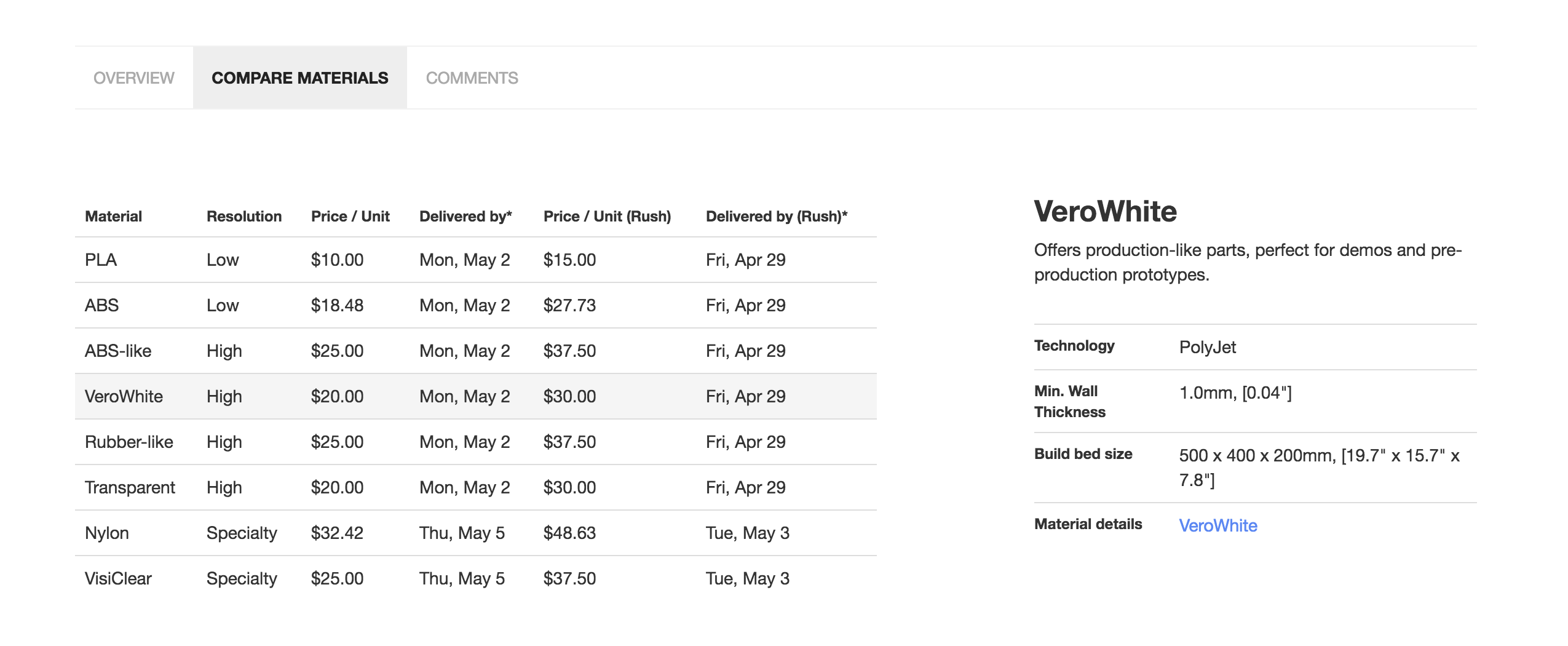
- For rib/gusset dimensioning, ensure that 3D-print wall thickness is within the recommended guidelines of the machine and/or process you will be using. If you’re using Fictiv’s platform, this information is under the compare materials tab in your part details page:
- On long, thin-walled sections, ribs may also prevent warpage induced during the fabrication process.
- For 3D printed ribs and 3D printed gussets, draft angle is not required, so wall thickness can be held constant where necessary.
- For production, keep in mind that injection molded parts have different requirements because the manufacturing challenges are much different.
And here are some design guidelines for injection molded parts:
- Rib thickness should be 60-80% of wall thickness.
- To increase stiffness, it’s advisable to increase the total number of ribs instead of the height (in some instances, this may not suffice).
- Rib height should be limited to three times the wall thickness or less, where possible (this may also be unavoidable in some load cases).
- Core out thick ribs and/or rib intersections to maintain constant wall thickness.
Main Takeaways
The thoughtful addition of ribs and gussets greatly improves plastic parts’ strength without adding too much material that can lengthen 3D printing times and cause manufacturing defects in injection molded parts. While they may not look like much, plastic ribs and plastic gussets go a long way to providing rigidity of your design.
Of course, the improper application of ribs provides little to no benefit. So, to get a feel for incorporating ribs is to play around with your designs and, of course, iterate early and often!
Sourcing Simplified – Start Your Next Project With Fictiv
For all your 3D printed and injection molded part manufacturing and finishing needs, Fictiv has you covered. We’re experts at producing custom mechanical parts, in a variety of materials, and we simplify custom part sourcing with intelligent, streamlined, automated workflows. Fictiv is your operating system for custom manufacturing that makes part procurement faster, easier, and more efficient.
Create an account and upload your part to see what our instant quote process, design for manufacturability feedback, and intelligent platform can do for you. Our 3D printing service can create your parts in as little as 24 hours, and our injection molding service manufactures T1 sample parts in as fast as 2 weeks!